Nutanix Resiliency – Part 2 – Converting from RF2 to RF3

In part 1 we discussed the ability of Nutanix AOS to rebuild from a node failure in a fast and efficient manner thanks to the Acropolis Distributed Storage Fabric (ADSF). In part 2 I wanted to show how a storage container can be converted from RF2 to RF3 and the speed at which the operation can be completed.

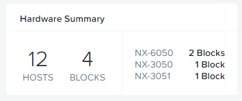
For this testing, only 12 nodes exist within the cluster.

ClusterSize

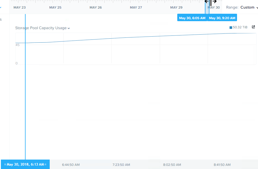
Let’s start with the storage pool capacity usage.

RF2Usage

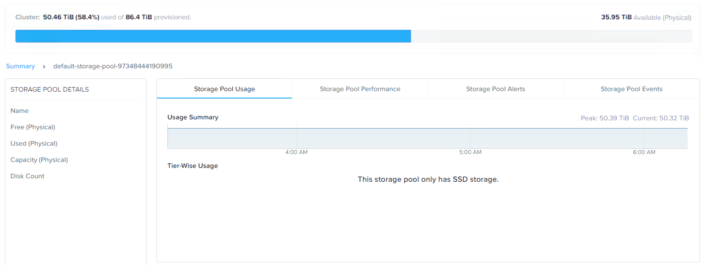
Here we see just over 50TB of storage usage across the cluster.

In converting to RF3, or put simply adding a third replica of all data, we need to ensure we have enough available capacity otherwise RF3 wont be in compliance.

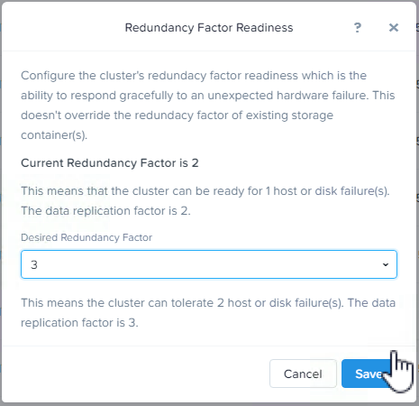
Next we increase the Redundancy Factor for the cluster (and metadata) to RF3. This enables the cluster to support RF3 containers, and to survive at least two node failures from a metadata perspective.

ReducdancyFactorCLuster

Next we increase the desired Storage Container to RF3.

Once the container is set to RF3, curator will detect the cluster is not in compliance with the configured redundancy factor and kick of a background task to create the additional replicas.

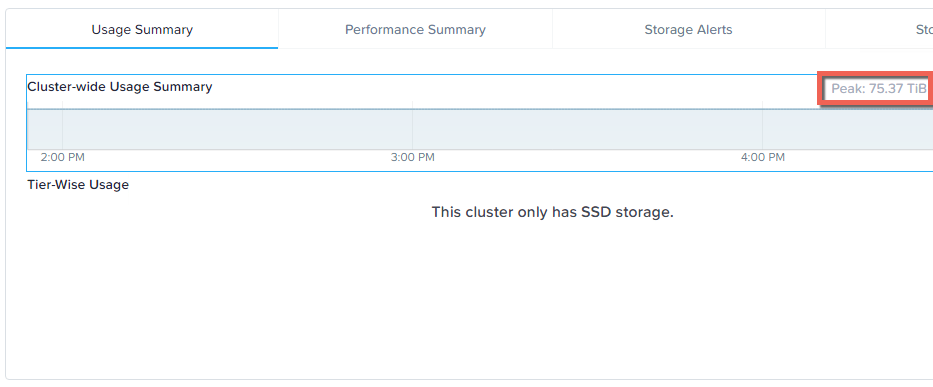
In this case, we started with approx 50TB of data in the storage pool, so this task will need to create 50% more replicas so we should end up with around 75TB of data.

Let’s see how long it took the cluster to create 25TB of data to comply with the new Redundancy Factor.

RF2toRF3on12NodeCluster

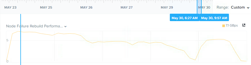
Here we see throughput of over 7GBps and the process taking less than 3 hours, so approx 8.3TB per hour. It is important to note that the cluster remained fully resilient at an RF2 level throughout the whole process, and had new writes been happening during this phase, they would all be protected with RF3.

Below is a chart showing the storage pool capacity usage increasing in a very linear fashion throughout the operation.

StoragePoolCapacityGrowth

Had the cluster been larger, it is important to note this task would have performed faster, as ADSF is a truely distributed storage fabric and the more node, the more controllers than participate in all write activity. For a great example of the advantage of adding additional nodes check out Scale out performance testing with Nutanix Storage Only Nodes.

Once the operation was completed we can see the storage pool capacity usage is at the expected 75TB level.

StoragePoolCapacityWithRF3

For those who are interested how hard Nutanix ADSF can drive the physical drives, I pulled some stats during the compliance phase.

StargateExtentStoreStats

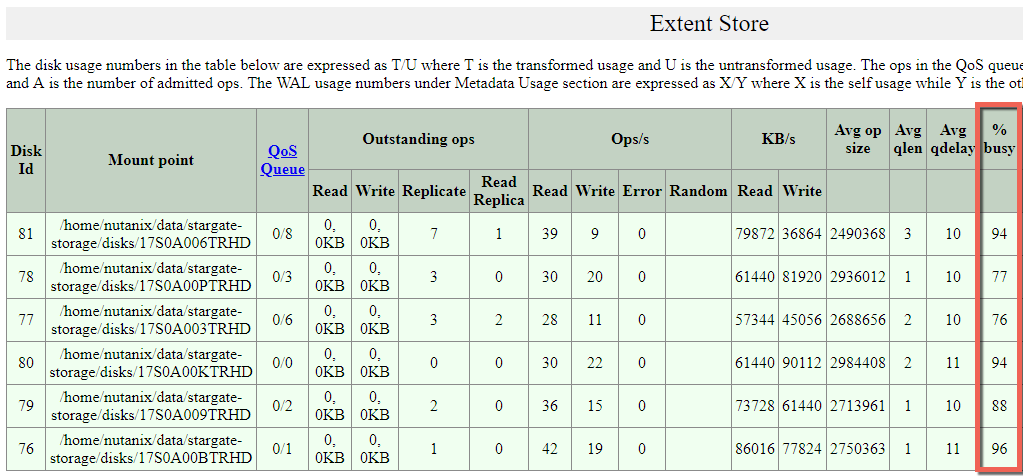
What we can see highlighted is that the physical drives are being driven at or close to their maximum and the read and write I/O is being performed across all drives, not just to a single cache drive and then offloaded to capacity drives like less intelligent HCI platforms.

Summary:

  • Nutanix ADSF can change between Redundancy levels (RF2 and RF3) on the fly
  • A compliance operation creating >25TB of data can complete in less than 3 hours (even on 5 year old equipment)
  • The compliance operation performed in a linear manner throughout the task.
  • A single Nutanix Controller VM (CVM) is efficient enough to drive 6 x physical SSDs at close to their maximum ability
  • ADSF reads and writes to all drives and does not use a less efficient cache and capacity style architecture.

Index:
Part 1 – Node failure rebuild performance
Part 2 – Converting from RF2 to RF3
Part 3 – Node failure rebuild performance with RF3
Part 4 – Converting RF3 to Erasure Coding (EC-X)
Part 5 – Read I/O during CVM maintenance or failures
Part 6 – Write I/O during CVM maintenance or failures
Part 7 – Read & Write I/O during Hypervisor upgrades
Part 8 – Node failure rebuild performance with RF3 & Erasure Coding (EC-X)
Part 9 – Self healing
Part 10: Nutanix Resiliency – Part 10 – Disk Scrubbing / Checksums

Write I/O Performance & High Availability in a scale-out Distributed File System

Following on from my recent post titled “Data Locality & Why is important for vSphere DRS clusters” I would like to discuss at a high level how Write I/O works in the Nutanix Distributed File System, how the solution ensures high availability in the event of a node failure and what impact a failure has on performance.

Lets start with a typical Write operation.

The below diagram shows a three (3) node Nutanix cluster with a Guest VM starting to perform write I/O, this is represented in a simplistic manor by the three (3) Diamonds (Red, Yellow and Purple)

NutanixWriteIOstart

The write I/O is written to the local SSD tier (as is every Write in a Nutanix environment) as shown below.

NutanixWriteDataWrittenLocal

Before acknowledging the write the Nutanix Controller VM (CVM) then replicates a copy of the data across the Nutanix Distributed File System.

The below diagram illustrates what this looks like in a three node cluster.

NutanixWriteSyncToOtherNodes

Once the data in successfully written to other nodes within the cluster, the Write acknowledgement is given. This ensures data is consistent and always protected.

In a Nutanix cluster, as Controllers (Nutanix CVMs) are scaled linearly with the ESXi hosts, Write I/O is then spread over more controllers, reducing the chance of contention in the environment at both a storage controller and network layer as each controller shares 2 x 10Gb connections per node.

In the event of a node failure, in a vSphere cluster, HA will restart the failed VM/s onto a surviving node in the cluster.

The VM will start-up and operate as normal and where data is not local to the node (as discussed in detail in my post  “Data Locality & Why is important for vSphere DRS clusters“) the data will initially be accessed over 10Gb before being replicated locally for future reads.

NutanixHAAfterWithDataAccess

All future writes for the VM/s which have been restarted by HA on different nodes will perform at a similar rate (if not the same rate) as they did before the failure depending on how many nodes are in the cluster. Where the Network is not a bottleneck, there should be minimal/no difference in write performance after a node failure.

The Nutanix cluster will also detect a node has failed, and ensure two copies of all data are available, and in the above example where only one copy of the data exists, the cluster will replicate the required data to ensure High Availability (“Replication Factor” of 2) is maintained.

As this replication is done across multiple controllers and nodes, it is much faster and lower impact than a traditional RAID rebuild which most of us will be familiar with.

The end state of this process looks like this.

NutanixHAEndState

So in conclusion using a “scale-out” storage controller solution like Nutanix ensures consistent high write performance even immediately following a node failure by eliminating the requirement for RAID style rebuilds which are disk intensive and can lead to “Double Disk Failures” and data loss.

The replication of data being distributed across all nodes in the cluster ensures minimal impact to each Nutanix controller, ESXi host and the network while ensuring the data is re-protected as soon as possible.

Related Articles

1. Data Locality & Why is important for vSphere DRS clusters


Example Architectural Decision – Advanced Power Management for vSphere Clusters with Business Critical Applications

Problem Statement

In a vSphere environment where Business Critical Applications have been successfully virtualized, should Advanced Power Management be used to help reduce data center costs?

Requirements

1. Fully Supported solution

2. Reduce data center costs where possible

3. Business Critical Application performance must not be significantly degraded

Assumptions

1. Supported Hardware

2. vSphere 5.0 or later

3. Admission Control is enabled with >= N+1 redundancy

Constraints

1. None

Motivation

1. Reduce Datacenter costs where possible with minimal/no impact to performance

Architectural Decision

Configure the BIOS to “OS Controlled”

Set ESXi Advanced Power Management to “Balanced”

Justification

1. Power savings can be realized with almost no impact to performance

2. The performance difference between “High performance” & “Balanced” options is insignificant however Power savings can be achieved reducing cost and environmental impacts

3. In the unlikely event of performance issues as a result of using the “Balanced” option, the BIOS is set to OS Controlled so ESXi can be updated without downtime during troubleshooting

4. Advanced Power Management Options (other than “High Performance” & “Balanced”) have proven to have excellent power savings but at a high cost to performance which is not suitable for Business Critical Applications

5. As HA Admission Control is used to provide >=N+1 redundancy, the ESXi hosts will generally not be fully utilized which will give Advanced Power Management opportunities to conserve power

6. The workloads in the cluster/s run 24/7 however demand is generally higher during business hours and some low demand or idle time exists

7. Even where only a small power saving is realized, if performance is not significantly impacted then a faster ROI can be achieved due to cost savings

Implications

1. Where performance issues exist using “Balanced” a vSphere administrator may need to change Advanced Power Management to “High Performance”

Alternatives

1. Use “High Performance”

2. Use “BIOS Controlled”

3. Do not use Advanced Power Management

4. Use Advanced Power Management in conjunction with DPM

Relates Articles

1. Power Management and Performance in ESXi 5.1 – By Rebecca Grider (@RebeccaGrider)

 AdvancedPowerManagement